How to write a Game Boy emulator – Part 6: Drawing the background
This post is part of a blog series about writing a Game Boy emulator.
This is where the fun begins: we're going to draw things on the screen. You'll need a drawing library like the SDL .
The graphics of the Game Boy are composed of three layers: the background, the window, and the sprites. The bios only uses the background, so we're gonna ignore the other layers.
The background tile map
The background is composed of 32x32=1024 tiles. Each tile is 8x8 pixels, so the background is 256x256 pixels.
| 0 | 1 | 2 | ... | 31 |
| 32 | 33 | 34 | ... | 63 |
| 64 | 65 | 66 | ... | 95 |
| ... | ... | ... | ... | ... |
| 992 | 993 | 994 | ... | 1023 |
The background tile map is a series of 1024 bytes in memory that determines the content of the background. Each byte represents a tile in the tile set (1024 tiles * 1 byte / tile = 1024 bytes).
There are in fact two tile maps that can be used. The background tile map used at any given moment is determined by bit 3 of the LCDC (LCD Control). It's a memory-mapped I/O location at 0xFF40.
| Bit 3 of the LCDC | Background tile map address range |
|---|---|
| 0 | 0x9800-0x9BFF (1024 bytes) |
| 1 | 0x9C00-0x9FFF (1024 bytes) |
The tile set
The tile set is a series of 4096 bytes in memory. It contains the pixel data for 256 tiles. Each tile is determined by 16 bytes (256 tiles * 16 bytes / tile = 4096 bytes).
Similarly to the tile map, there are two tile sets that can be used.
| Bit 4 of the LCDC | Tile set address range |
|---|---|
| 0 | 0x8800-0x97FF (4096 bytes) |
| 1 | 0x8000-0x8FFF (4096 bytes) |
You may have noticed that the two tile sets overlap. This is fine since we're only using one at a time anyway.
Each byte in the tile map corresponds to a tile in the tile set. There is a subtlety though. If we're using tile set #1 (0x8000-0x8FFF), everything works as expected: the byte in the tile map is interpreted as an unsigned index in the tile set starting at 0x8000. If we're using tile set #0 (0x8800-0x97FF), then the byte in the tile map is interpreted as a signed index in the tile set centered at 0x9000. The two tables below should make it clearer.
| Byte in the tile map | Address range of the tile in the tile set |
|---|---|
| 0 | 0x8000-0x800F (16 bytes) |
| 1 | 0x8010-0x801F (16 bytes) |
| 2 | 0x8020-0x802F (16 bytes) |
| ... | ... |
| 255 | 0x8FF0-0x8FFF (16 bytes) |
| Signed byte in the tile map | Address range of the tile in the tile set |
|---|---|
| -128 | 0x8800-0x880F (16 bytes) |
| -127 | 0x8810-0x881F (16 bytes) |
| -126 | 0x8820-0x882F (16 bytes) |
| ... | ... |
| 0 | 0x9000-0x900F (16 bytes) |
| ... | ... |
| 127 | 0x97F0-0x97FF (16 bytes) |
Tiles
A tile is an 8x8 square of pixels whose colors are determined by 16 bytes. It takes 2 bytes to define an 8x1 line of pixels, and 2 bits to define the color of one pixel (8 lines / tile * 8 pixels / line * 2 bits / pixel * 1 byte / 8 bits = 16 bytes).
| Byte | Tile line |
|---|---|
| 0 | 0 (top) |
| 1 | |
| 2 | 1 |
| 3 | |
| 4 | 2 |
| 5 | |
| ... | ... |
| ... | |
| 14 | 7 (bottom) |
| 15 |
| Pixel (left ↔ right) | 0 | 1 | 2 | 3 | 4 | 5 | 6 | 7 |
|---|---|---|---|---|---|---|---|---|
| Bit | 7 | 6 | 5 | 4 | 3 | 2 | 1 | 0 |
| Low bits (byte n) | l7 | l6 | l5 | l4 | l3 | l2 | l1 | l0 |
| High bits (byte n + 1) | h7 | h6 | h5 | h4 | h3 | h2 | h1 | h0 |
| Palette index | h7l7 | h6l6 | h5l5 | h4l4 | h3l3 | h2l2 | h1l1 | h0l0 |
When we combine two bits as shown above, we don't get a color, we get a palette index. We translate a palette index to a color using the BGP. The BGP or the BackGround Palette is a memory-mapped I/O location at 0xFF47.
| Palette index | 3 | 2 | 1 | 0 | ||||
|---|---|---|---|---|---|---|---|---|
| Bit | 7 | 6 | 5 | 4 | 3 | 2 | 1 | 0 |
| BGP (0xFF47) | b7 | b6 | b5 | b4 | b3 | b2 | b1 | b0 |
| Color index | b7b6 | b5b4 | b3b2 | b1b0 | ||||
| Color index | Grayscale palette | Green palette |
|---|---|---|
| 0b00 | White | |
| 0b01 | Light grey | |
| 0b10 | Dark grey | |
| 0b11 | Black |
When to draw
The Game Boy draws a frame every 70 224 clock cycles. The clock runs at 4.19 4.194304 MHz, which means 60 frames per second approximately (4 194 304 cycles / s * 1 frame / 70 224 cycles ≈ 59.72750 frames / s).
The Game Boy doesn't draw a whole frame at once. It draws the screen pixel per pixel, from top to bottom, left to right. It takes 456 cycles to draw a scanline, and there are 154 of them. The screen has 144 lines. The last 10 scanlines are not visible: they only exist timing-wise.
Previously we made memory location 0xFF44 (LY) always return 144. We did that because the bios waits for scanline 144 which marks the beginning of the V-blank period. You should change that and increment LY every 456 cycles. Its value wraps back to 0 after 153. This will ensure the bios doesn't run too fast.
| Scanline | Cycles | Period | Cycles | Period | Cycles |
|---|---|---|---|---|---|
| 0 | 456 | Visible scanlines | 65 664 | Frame | 70 224 |
| 1 | 456 | ||||
| 2 | 456 | ||||
| ... | ... | ||||
| 143 | 456 | ||||
| 144 | 456 | V-blank | 4 560 | ||
| 145 | 456 | ||||
| 146 | 456 | ||||
| ... | ... | ||||
| 153 | 456 |
Every CPU instruction takes a variable number of cycles to execute. For the moment we'll just assume all instructions take 4 cycles to execute.
Also we're going to draw the whole screen every 70 224 cycles, and not scanline by scanline. This is not how it works, but it's good enough right now.
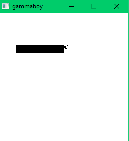
If you display the whole 256x256 background, this is what you should get. Either left or right depending on what you return at memory locations 0x0104-0x0133.
Scrolling
The background is 256x256 pixels, but the Game Boy's screen can only display 160x144 pixels. What does this mean? It means that we cannot display the whole background at once. We have to choose what part of it to show.
SCX (Scroll X) and SCY (Scroll Y) are two memory-mapped I/O locations at 0xFF43 and 0xFF42 that do just that. The point (SCX, SCY) in the background is the upper left corner of the screen.
The bios modifies SCY to scroll the Nintendo logo as you can see in the video below.
My emulator is too slow!
Make sure you are not drawing frames too frequently. Your emulator should draw a frame every 154 * 456 = 70 224 cycles, not after every instruction.
Same thing about events (keypresses, mouse clicks, etc.). You should process events every frame or so, not after every instruction.
Make sure you're using your drawing library efficiently. You have to draw your frames pixel by pixel, but you should do it efficiently. Read the documentation of your drawing library if you need to. It's easy to shoot yourself in the foot performance-wise if you're careless.
The bios runs in about 5 seconds on a real Game Boy. Your emulator should not be slower than that. If you measure the execution time of your emulator, make sure you measure the right thing. Don't include the time it takes for your drawing library to initialize itself and create a window. gammaboy takes roughly 1s to execute the bios.
My emulator is too fast!
This is the kind of problems I like to have. It's to be expected: modern computers are fast, and the Game Boy is old. Your emulator should run circles around it.
We'll have to slow down the emulator at some point, otherwise games are going to run too fast, but I don't really mind right now.
This being said, make sure you don't always return 144 at 0xFF44, otherwise the bios will run too fast.