How to write a Game Boy emulator – Part 3: Fetch, decode, execute
This post is part of a blog series about writing a Game Boy emulator.
The fetch-decode-execute cycle is how every computer works:
- First fetch the bytes from memory that form the current instruction.
- Decode the fetched bytes into a concrete instruction.
- Execute the decoded instruction.
- Repeat the steps above for the next instruction.
The Program Counter holds the address of the current instruction in memory. Its value at startup in the Game Boy is 0x0000.
The Game Boy has a 16-bit address space, meaning that the lowest possible address is 0x0000, and the highest is 0xFFFF. Each address corresponds to a byte in memory. The bios is mapped to the first 256 bytes of the address space.
Let's look at the bios in a hexadecimal editor:
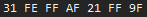
Each CPU has its own instruction set . This means that the available instructions differ from one CPU to the next, and how they are encoded differs too.
The processor in the Game Boy is the Sharp LR35902, which is roughly a superset of the Intel 8080, and roughly a subset of the Z80. Unfortunately I don't think it has any official, publically available documentation, so I use GBZ80Opcodes.pdf to decode bytes into instructions. Let's look for the entry corresponding to 0x31:
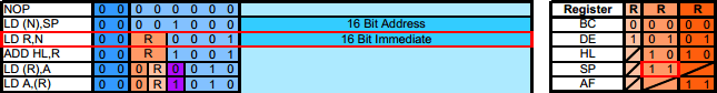
We can see that 0x31=0b00110001 corresponds to LD R,N where R=0b11=SP, and where N is the 16-bit immediate . It's a 3-bytes long instruction. The first byte is the opcode. The second and third bytes are the 16-bit immediate. Instructions on the Game Boy can be 1, 2, or 3-bytes long.
The Game Boy is little-endian . This means that the immediate value here is equal to 0xFFFE (and not 0xFEFF), which gives us the instruction LD SP,0xFFFE.
An instruction is composed of an operation and of operands. You can think of the operation as a function, and of the operands as the arguments to that function. In our case, LD is the operation, and SP and N are the operands. On the Game Boy, operations can have 0, 1, or 2 operands.
LD is the load instruction. You can think of it as the assignment instruction. It takes the value of the second argument, and puts it in the first argument. This means that the instruction LD SP,0xFFFE assigns the value 0xFFFE to SP.
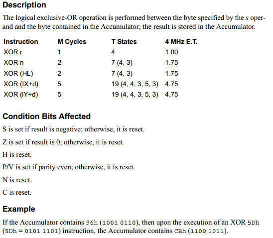
The next byte in the bios is 0xAF and it corresponds to the instruction XOR A. XOR is the "exclusive or" operation.
We're gonna need to look at another document, UM0080.pdf to know what XOR does exactly. It's the official documentation for the Z80, so it's very accurate and well done, but keep in mind that the CPU in the Game Boy is not a Z80, so you can't take it literally. As of this writing, the last update to that document was in August 2016, which I think is awesome: I mean, I can't imagine that a processor from the 70s is widely used anymore, but they still update its documentation for typos and errors. For now, you only need to know that XOR has the same behavior in the Z80 and in the Game Boy.
This gives something like this once translated into code:
/// UM0080.pdf rev 11 p175 / 332
fn XOR<T>(st: &mut State, x: T) where T: R<u8> {
	let new_value: u8 = A.get(st) ^ x.get(st);
	A.set(st, new_value);

	let result_is_zero: bool = A.get(st) == 0x00;
	Flag::Z.set(st, result_is_zero);
	Flag::N.set(st, false);
	Flag::H.set(st, false);
	Flag::C.set(st, false);
}
The next byte in the bios is 0x21 which corresponds to LD HL,N where N is the 16-bit immediate value.
And that's it for this post. We're only emulating the first 7 bytes of the bios, but it still requires a fair amount of code.
The code
There are many ways you can structure your code. You can look at mine for inspiration. What is certain though is that your emulator should have some sort of logging capability. You need to know what's going on inside your emulator, otherwise it's going to be undebuggable. It should output something like this:
PC=0x0000 AF=0x0000 BC=0x0000 DE=0x0000 HL=0x0000 SP=0x0000
 0x31 0xFE 0xFF | LD SP, 0xFFFE
PC=0x0003 AF=0x0000 BC=0x0000 DE=0x0000 HL=0x0000 SP=0xFFFE
 0xAF           | XOR A
PC=0x0004 AF=0x0080 BC=0x0000 DE=0x0000 HL=0x0000 SP=0xFFFE
 0x21 0xFF 0x9F | LD HL, 0x9FFF
PC=0x0007 AF=0x0080 BC=0x0000 DE=0x0000 HL=0x9FFF SP=0xFFFE
thread 'main' panicked at 'Unknown opcode 0x32=0b00110010 at PC=0x0007.'